
Roughing
Choose the largest safe diameter with chip space and edge strength suited to the engagement and stock allowance.
APPLICATION · MOLD STEEL
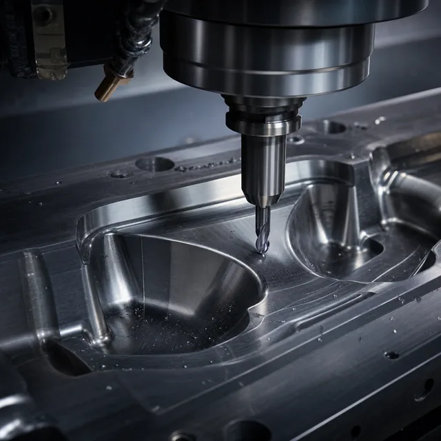
Mold work needs separate roughing and finishing decisions. Match the hardened-steel window, cavity depth, corner radius and holder rigidity to a published BOFA end-mill series before requesting cutting data.
DIRECT ANSWER
For mold steel, separate roughing and finishing decisions, then match the measured hardness, cavity reach, corner radius and holder rigidity to a BOFA HRC55, HRC60 or HRC65 series. Use the published chart and a representative cavity trial before production.
QUERY FAN-OUT COVERAGE
| Field | What to record |
|---|---|
| Sample size | No public BOFA sample count is claimed; record the number of cavities, walls or test features used for acceptance. |
| Test environment | Use the production machine, holder, gauge length, CAM strategy and measured workpiece hardness. |
| Controlled variables | Keep series, diameter, cutting length, neck, stick-out, engagement, allowance and toolpath revision fixed during comparison. |
| Measurements | Record spindle load, chatter, dimensional result, surface finish and first wear location on the cavity feature. |
APPLICATION BRIEF
These are selection inputs, not blanket cutting claims. Confirm the exact series chart and the actual machine setup before production.
Pre-hardened and hardened mold steels. State the exact grade, heat-treatment condition and measured hardness; HRC55, HRC60 and HRC65 series names indicate intended windows, not a substitute for the drawing.
Cavity roughing, wall finishing, 3D profiling, corner finishing and small-feature machining. Include the deepest feature and smallest internal radius.
SELECTION CHECKS
Put the following decisions in the same document as the drawing or sample. It keeps engineering, purchasing and quality aligned.
Choose the largest safe diameter with chip space and edge strength suited to the engagement and stock allowance.
Use flat, corner-radius or ball nose geometry from the surface and internal-corner requirement.
Specify cutting length, neck relief, gauge length and the shortest setup that reaches the cavity.
Record tool overhang, runout, spindle load, finish and first wear on a representative test feature.
PUBLISHED PRODUCTS
PEOPLE ALSO ASK
Answers describe the information needed for a sound decision. They do not replace the tool maker’s chart or a controlled first pass.
HRC55 describes an intended workpiece hardness window for the series. Confirm the actual alloy, heat-treatment condition, feature, reach, coating and cutting chart before production.
They can, but separate tools often control stock removal, edge strength and surface finish better. Decide from the feature, allowance and cycle-time target.
Long gauge length, holder runout, flexible workholding and a high unsupported neck are common causes. Check the setup and toolpath before reducing every parameter.
READY TO COMPARE?
Attach the drawing, current tool photo or process notes. BOFA will confirm the series, interface and quotation route.
Open technical RFQ →TECHNICAL SELECTION NOTES
Use these notes to frame a first selection. Final cutting data must come from the exact BOFA series chart and a controlled test on the target machine.
Mold work is a sequence of stock removal, cavity access and surface finishing. The measured hardness and the smallest feature should drive the series choice.
A repeatable trial makes a mold-tool recommendation easier to audit and scale.