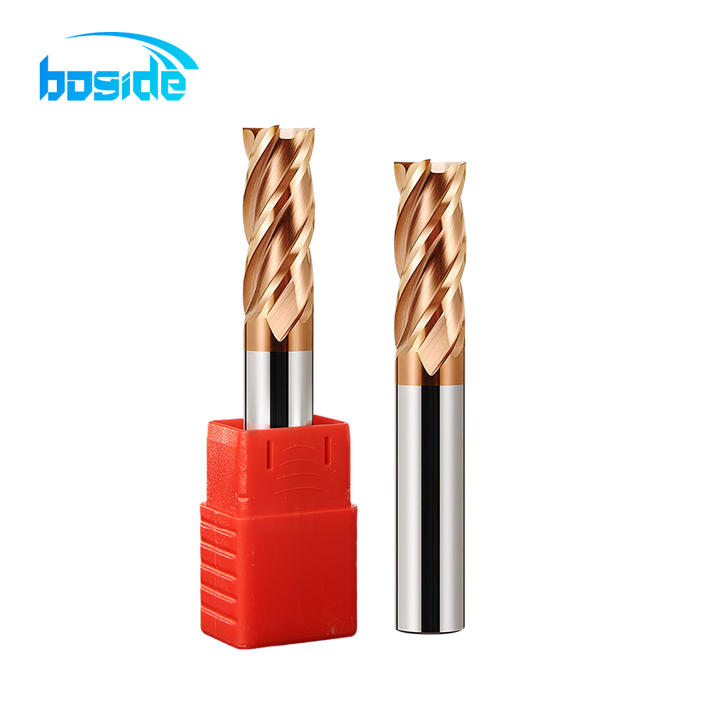
SERIES OVERVIEW
Carbide HRC55 4-Flute Flat End Mill for Hardened Mold Steel
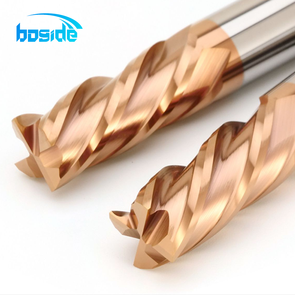
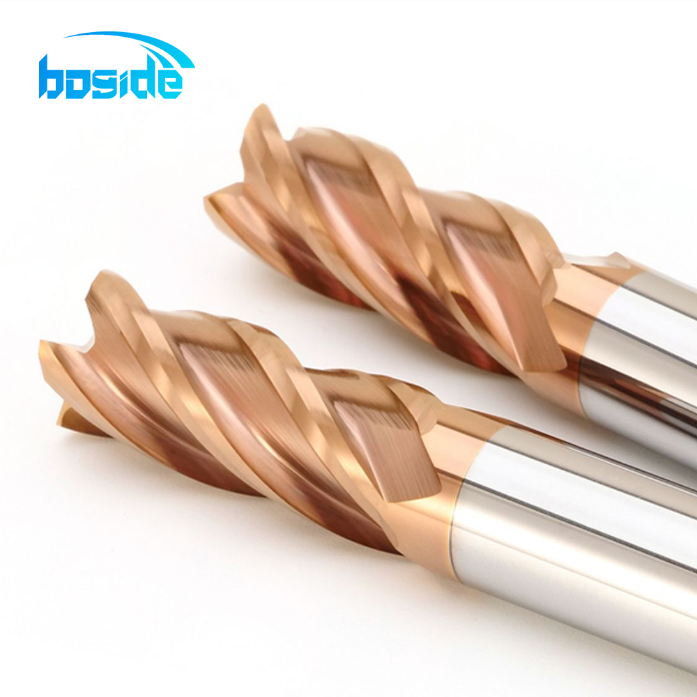
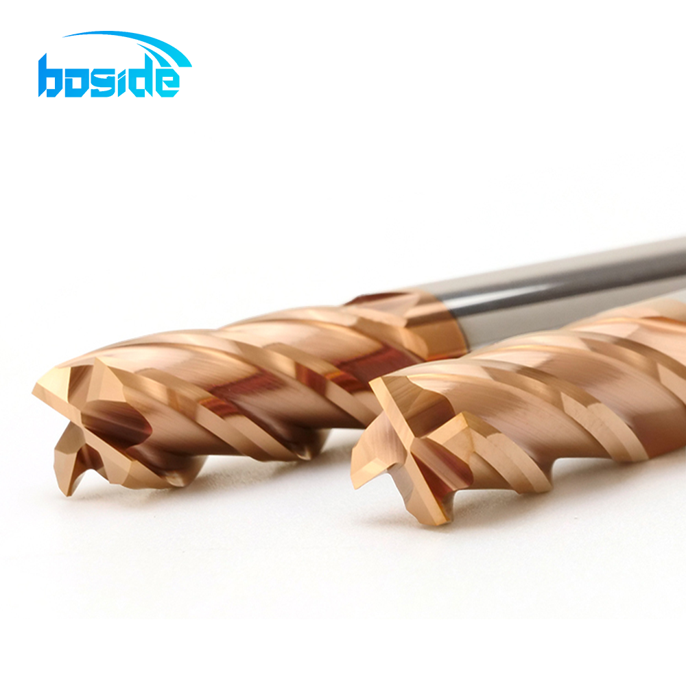
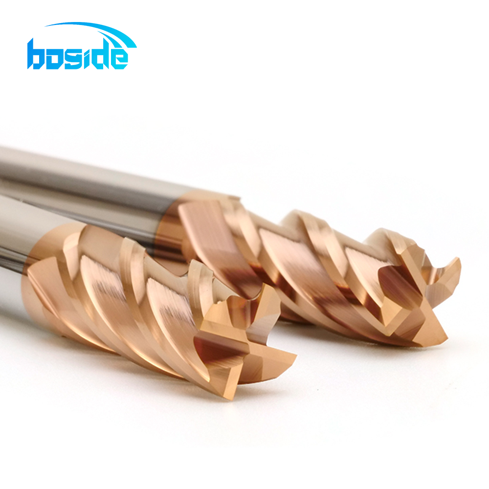
BOFA HRC55 flat end mills feature a 4-flute cutting design and 55° helix angle for precision milling. This series covers practical diameters from Ø1 to Ø20 mm.
Key configuration options
- HRC55 flat end mill series
- 4-flute design with 55° helix angle
- Diameter range: Ø1–20 mm
- Multiple cutting lengths and overall lengths
Standard specifications
| Product Model | Diameter D (mm) | Cutting Length H (mm) | Shank C (mm) | Overall Length L (mm) | Flutes | Helix Angle |
|---|---|---|---|---|---|---|
| D1*3*D4*50L*4F | 1 | 3 | 4 | 50 | 4 | 55° |
| D1.5*4.5*D4*50L*4F | 1.5 | 4.5 | 4 | 50 | 4 | 55° |
| D2*6*D4*50L*4F | 2 | 6 | 4 | 50 | 4 | 55° |
| D2.5*7.5*D4*50L*4F | 2.5 | 7.5 | 4 | 50 | 4 | 55° |
| D3*9*D3*50L*4F | 3 | 9 | 3 | 50 | 4 | 55° |
| D3*9*D4*50L*4F | 3 | 9 | 4 | 50 | 4 | 55° |
| D3*12*D3*75L*4F | 3 | 12 | 3 | 75 | 4 | 55° |
| D3*15*D3*100L*4F | 3 | 15 | 3 | 100 | 4 | 55° |
| D3.5*10*D4*50L*4F | 3.5 | 10 | 4 | 50 | 4 | 55° |
| D4*10*D4*50L*4F | 4 | 10 | 4 | 50 | 4 | 55° |
| D4*16*D4*75L*4F | 4 | 16 | 4 | 75 | 4 | 55° |
| D4*20*D4*100L*4F | 4 | 20 | 4 | 100 | 4 | 55° |
| D5*13*D5*50L*4F | 5 | 13 | 5 | 50 | 4 | 55° |
| D5*13*D6*50L*4F | 5 | 13 | 6 | 50 | 4 | 55° |
| D5*20*D5*75L*4F | 5 | 20 | 5 | 75 | 4 | 55° |
| D5*25*D5*100L*4F | 5 | 25 | 5 | 100 | 4 | 55° |
| D6*15*D6*50L*4F | 6 | 15 | 6 | 50 | 4 | 55° |
| D6*24*D6*75L*4F | 6 | 24 | 6 | 75 | 4 | 55° |
| D6*30*D6*100L*4F | 6 | 30 | 6 | 100 | 4 | 55° |
| D6*45*D6*150L*4F | 6 | 45 | 6 | 150 | 4 | 55° |
| D8*20*D8*60L*4F | 8 | 20 | 8 | 60 | 4 | 55° |
| D8*30*D8*75L*4F | 8 | 30 | 8 | 75 | 4 | 55° |
| D8*35*D8*100L*4F | 8 | 35 | 8 | 100 | 4 | 55° |
| D8*50*D8*150L*4F | 8 | 50 | 8 | 150 | 4 | 55° |
| D10*25*D10*75L*4F | 10 | 25 | 10 | 75 | 4 | 55° |
| D10*40*D10*100L*4F | 10 | 40 | 10 | 100 | 4 | 55° |
| D10*60*D10*150L*4F | 10 | 60 | 10 | 150 | 4 | 55° |
| D12*30*D12*75L*4F | 12 | 30 | 12 | 75 | 4 | 55° |
| D12*45*D12*100L*4F | 12 | 45 | 12 | 100 | 4 | 55° |
| D12*60*D12*150L*4F | 12 | 60 | 12 | 150 | 4 | 55° |
| D14*45*D14*100L*4F | 14 | 45 | 14 | 100 | 4 | 55° |
| D14*70*D14*150L*4F | 14 | 70 | 14 | 150 | 4 | 55° |
| D16*45*D16*100L*4F | 16 | 45 | 16 | 100 | 4 | 55° |
| D16*75*D16*150L*4F | 16 | 75 | 16 | 150 | 4 | 55° |
| D18*45*D18*100L*4F | 18 | 45 | 18 | 100 | 4 | 55° |
| D18*75*D18*150L*4F | 18 | 75 | 18 | 150 | 4 | 55° |
| D20*45*D20*100L*4F | 20 | 45 | 20 | 100 | 4 | 55° |
| D20*75*D20*150L*4F | 20 | 75 | 20 | 150 | 4 | 55° |
Important: Please confirm the final size, workpiece material and cutting application with BOFA before ordering.
Carbide grade, geometry and interface
Use the published series geometry and request any unlisted metallurgy or quality value from BOFA before production.
| Engineering field | Published value / required confirmation |
|---|---|
| Substrate | Solid carbide; exact grade code to be confirmed on the BOFA datasheet. |
| Grain size | Not in the current chart; request the series or batch datasheet. |
| Cobalt content | Not in the current chart; request the series or batch datasheet. |
| Coating | Coating family and thickness are not in the current chart; confirm for the material and diameter. |
| Helix angle | 55° (published for this series) |
| Workpiece material | Mould steel and carbon/alloy steel applications; confirm the exact grade and measured hardness before cutting. |
| Diameter / length tolerance | Not published in the current chart; specify the required tolerance in the RFQ. |
| Tool-tip runout | Not published in the current chart; specify the measurement position and target runout. |
| Shank / machine interface | State shank diameter, spindle taper, holder type and gauge length. |
| Insert model match | Not applicable: solid-carbide end mill with no replaceable insert. |
Frequently asked questions
When should I choose a flat end mill?
Choose a flat end mill for slots, pockets, planar walls and general profiling. Use a ball nose for 3D contours and a corner-radius tool when the edge needs additional support.
Which workpiece materials can I machine?
Send the exact material grade—mould steel, carbon/alloy steel, stainless steel, cast iron, aluminium or another alloy—and its measured HRC/HB. Geometry and coating must be confirmed for the actual material.
What carbide grade, grain size, cobalt content and coating are supplied?
Those values are not in the current product chart. Request the BOFA series or batch datasheet and do not assume a grade, cobalt percentage or coating family that has not been confirmed.
How should I choose spindle speed, feed and depth of cut?
Provide diameter or radius, material and hardness, flute count, overhang, holder, operation, coolant and target finish. BOFA can then return rpm, feed per tooth, table feed, axial depth and radial engagement for the setup.
Which holder and machine interface are required?
State the spindle taper, holder type, gauge length and target tool-tip runout. The shank must match the holder, and the shortest safe overhang should be used for a stable cut.
What tolerance and runout data should be specified?
State the diameter/length tolerance, measurement position and tool-tip runout target in the RFQ. The current chart does not publish guaranteed values, so BOFA will confirm them before quotation.
Technical RFQ — model and size pre-filled
Each linked size row opens the RFQ with the exact model and dimensions. Include material, hardness, rpm, feed, ap/ae, coolant, holder interface, tolerance, runout, quantity and drawing.
ENGINEERING DATA
Selection data for a technical quotation.
Use the published chart and series attributes where available. For a safe recommendation, send the fields below; BOFA will return the matching geometry, insert and cutting-condition card for your machine.
| Decision field | What to provide or verify | BOFA quotation output |
|---|---|---|
| Published series attributes | HRC55 · 4 Flute · Ø1–20 mm · 55° Helix | Confirm the exact model and size chart row |
| Workpiece material and hardness | Exact grade plus measured HRC or HB; include stainless, cast iron, aluminium or mould-steel condition | Recommended grade, geometry and coating |
| Speed, feed and depth | Target RPM or cutting speed, feed units / fz / Vf, axial ap and radial ae | Condition card for the selected diameter and operation |
| Geometry and reach | Diameter or ball radius, flute count, cutting length, overall length, helix and coating | Compatible standard or custom configuration |
| Insert and interface | For indexable tools: body model, insert code, screw and wrench. For solid tools: spindle taper, shank, holder and gauge length | Compatibility check before ordering |
| Tolerance and runout | Required tool-tip runout and diameter / length tolerance | Achievable value confirmed on drawing or datasheet |
| Cooling and maximum engagement | Dry, air blast, MQL or flood coolant with pressure / flow; state required machining depth | Safe engagement guidance; do not infer a limit from cutting length alone |
PRODUCT DETAILS
Images, configurations and size charts.